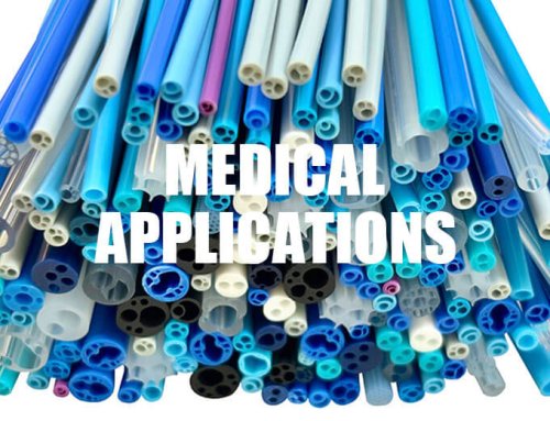
FEP heat shrink tubing (Fluorinated Ethylene Propylene heat-shrink tubing) is widely utilized in high-tech fields such as semiconductors, renewable energy, and medical applications due to its resistance to high temperatures (-200°C to 200°C), chemical corrosion, and low dielectric loss. However, improper operation can lead to issues such as uneven shrinking, sealing failure, or even material damage.
Mochitek provides a step-by-step operational guide, an analysis of five common mistakes, and industry application scenarios to help you quickly advance from a novice to a professional user.
I.Core Characteristics of FEP Heat-Shrink Tubing (Why Proper Usage is Crucial)
- Temperature Resistance: Continuous operating temperature of 200°C with short-term tolerance up to 300°C (superior to PVC and rubber).
- Chemical Inertia: Resistant to strong acids (such as concentrated sulfuric acid, hydrofluoric acid), strong bases, and organic solvents.
- Electrical Properties: Dielectric strength >20kV/mm, suitable for high-voltage insulation applications.
- Shrinkage Ratio: 3:1,1.6:1or 2:1, accommodating various size requirements.
Consequences of Improper Usage:
- Insufficient Temperature→ Incomplete Shrinkage → Seal Failure
- Excessive Heating→ Material Decomposition → Release of Toxic Gases
- Improper Cleaning→ Interface Contamination → Decreased Adhesion Strength
II.Six Steps for Proper Usage of FEP Heat-Shrink Tubing
Step 1: Selection – Matching Size and Performance
(1)Diameter Formula:
D1 = D2 × S
Where D1 represents the inner diameter before shrinking,D2 represents the outer diameter of the object to be covered,and S represents shrinkage ratio(such as 1.3,1.6,2,etc)
(2)Wall Thickness Selection:
| Application Scenario | Recommended Wall Thickness |
| General Insulation | 0.3-0.5mm |
| Chemical Protection | 0.5-1.0mm |
| High-Voltage Sealing | ≥1.0mm |
Step 2: Surface Pretreatment – Cleaning and Polishing
(1)Tools: Non-woven cloth + isopropanol (acetone is prohibited as it may corrode FEP).
(2)Key Points:
- Remove burrs from metal surfaces to avoid puncturing the heat-shrink tubing.
- Lightly polish plastic surfaces with 200-grit sandpaper to enhance adhesion.
Step 3: Cutting and Pre-installation
(1)Length Formula:
L1 = L2 + 2*a
Where L1 represents heat shrink tubing length,L2 represents length of the area to be covered,and a represents allowance on both ends.
(2)Tips:
- Use a sharp blade for cutting to avoid compression deformation.
- If it is difficult to slide the tubing onto the object, briefly heat the tube opening to soften it.
Step 4: Heating and Shrinkage – Precise Control of Temperature and Time
(1)Tool Selection:
| Tool | Application Scenario | Temperature Setting |
| Temperature-controlled hot air gun | Small batches/precision operations | 280-320°C |
| Infrared tunnel furnace | Mass production | 290°C ± 5°C |
| Heat-shrink oven | Complex geometries | Segmented heating |
(2)Operation Process:
- Start from one end and move in a spiral pattern to evenly heat (speed: 5-10cm/s).
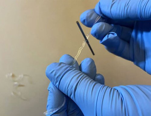
- When the transparent FEP turns translucent, it indicates the start of shrinkage.
- After shrinkage is complete, maintain heating for 2-3 seconds to eliminate internal stress.

Step 5: Cooling and Shaping
(1)Natural Cooling: Allow to cool naturally for 3-5 minutes. Avoid forced cooling to prevent thermal stress cracking.
(2)Acceptance Criteria:
- Smooth surface with no bubbles, wrinkles, or burn marks.
- Uniform wall thickness after shrinkage (tolerance ±5%).
Step 6: Performance Testing (Optional)
(1)Industrial-Grade Testing:
- Withstand Voltage Test: Apply 2 times the rated voltage for 1 minute with no breakdown.
- Airtightness Test: Maintain a pressure of 0.5MPa for 30 minutes with a leakage rate <1%.
III. Five Common Errors and Solutions
| Error Phenomenon | Cause Analysis | Solution |
| Surface Bubbling After Shrinking | The Coated Object Contains Volatile Substances | Clean, Dry, and Then Apply |
| End Recoil | Uneven Heating / Insufficient Allowance | Leave an Additional 10mm on Both Ends and Heat Thoroughly |
| Partial Burning | Excessively High Hot Air Gun Temperature | Use PID Temperature Control Equipment |
| Poor Adhesion | Surface Not Sanded or Cleaned | Apply Fluorine-Based Primer After Pretreatment |
| Incomplete Shrinking | Insufficient Temperature or Time | Increase to 320°C and Extend Heating Time |
IV.Industry Application Scenarios
1.Photovoltaic Inverters – UV Resistance and Weatherability
- Problem: Outdoor photovoltaic junction boxes experience powdering of heat-shrinkable tubing due to UV exposure.
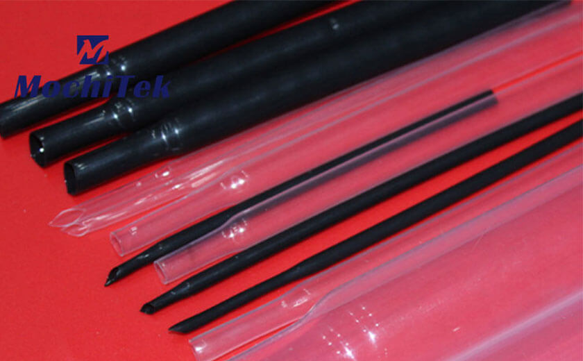
- Solution: Use black FEP heat-shrinkable tubing (with carbon black UV inhibitor added).
2.Chemical Pipelines – HF Acid-Resistant Sealing
- Problem: Corrosion and leakage at joints in HF acid transfer pipelines.
- Solution: Dual-layer structure: Inner layer of PTFE lining + outer layer of FEP heat-shrinkable tubing.
3.High-Frequency Communications – Low Dielectric Loss Applications
- Problem: Signal attenuation in 5G base station antennas due to dielectric loss.
- Solution: Adopt FEP heat-shrinkable tubing with a dielectric constant (ε) of less than 2.1.
If you have any questions or needs regarding our FEP/PTFE/PVDF heat shrink tube, please feel free to contact us. Our contact information is as follows:
Phone: +86 15956561251
Email: ruby@mochi.org.cn
Looking forward to working with you to create a bright future!